
MQTT is a messaging protocol widely used in IoT projects. However, for beginners, it can be a challenge to get an ESP32 MQTT setup running. Hence, in this tutorial, I’ll show you how to set up an MQTT Broker on a Linux device, such as the Raspberry Pi Zero 2 W, that allows an ESP32 to publish photoresistor (sensor) readings to a topic that another ESP32 subscribes to, thereby controlling an LED.
Keep Reading!
What is MQTT and How Does It Work?
MQTT (Message Queuing Telemetry Transport) is a wireless communication protocol that follows a client-broker architecture:
- Clients (e.g., your ESP32) either publish messages to a topic or subscribe to topics in order to receive messages.
- The Broker (e.g., Mosquitto on a Raspberry Pi) handles all the message routing so that a client only receives messages from a topic that it is subscribed to.
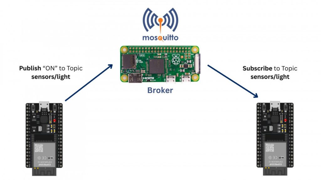
In our example that we will be building, one ESP32 uses a photoresistor to measure the ambient brightness and publish a message to the topic “sensors/light” if the brightness is above or below a certain threshold. The other ESP32 subscribes to that topic and receives the message. Depending on whether the brightness is below or above the threshold, it will turn an LED on or off.
In between the two ESP32s, we will use a Raspberry Pi with Mosquitto installed that acts as a broker and forwards the messages.
What You’ll Need
Hardware Needed
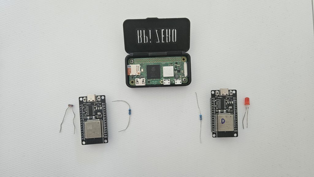
- 2x ESP32 Development Boards
- 1x Raspberry Pi Zero 2 W (or any other Pi / Linux device)
- 1x Photoresistor (LDR)
- 1x 10kΩ resistor
- 1x LED (+ 220Ω resistor)
Software Needed
- Arduino IDE or PlatformIO set up to work with ESP32
- Raspberry Pi OS installed on your Raspberry Pi
- PubSubClient library for ESP32 (installation covered in this guide)
- Mosquitto MQTT broker (installation covered in this guide)
Setting Up the Mosquitto MQTT Broker on a Raspberry Pi
In this guide, I will use a Raspberry Pi Zero 2 W as a broker. However, you can use any other Raspberry Pi or Linux device as well. Simply connect to your Pi via SSH and run the following commands in the terminal.
To handle the MQTT messages, we need to install a program called Mosquitto.
sudo apt update
sudo apt install -y mosquitto mosquitto-clientsNext, we start Mosquitto and enable it so it automatically runs on system start.
sudo systemctl enable mosquitto
sudo systemctl start mosquittoLast but not least, let’s check whether Mosquitto is running:
sudo systemctl status mosquittoIf you can see the status “active (running)“, you’ve successfully installed Mosquitto, and the broker will now be accessible on the Pi’s local IP address at port 1883.
In case you don’t know, you can find out the Pi’s local IP address using the following command:
hostname -IInstalling the PubSubClient Library for ESP32
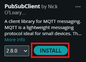
In the Arduino IDE (or PlatformIO), we need to install the PubSubClient library by Nick O’Leary to connect to an MQTT broker and subscribe and publish to MQTT topics.
To do so, open your Arduino IDE, click Sketch > Include Library > Manage Libraries …, and search for PubSubClient.
Wiring the Photoresistor
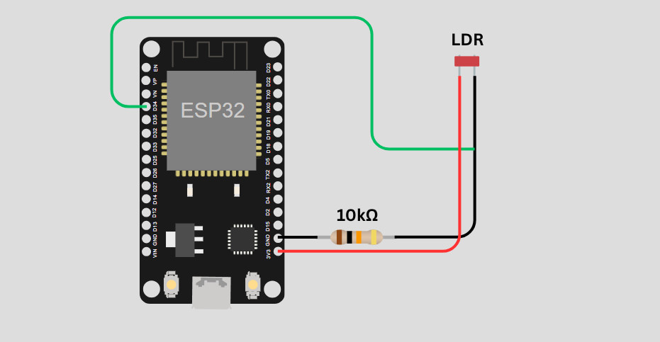
Connect one of the Photoresistor’s pins to 3.3V on the ESP32. The other pin is connected to an ADC pin of ADC1 (e.g., GPIO 34) and to ground (GND) via a 10kΩ resistor.
Don’t use a pin connected to the second ADC (Analog to Digital Converter), as this one is turned off when Wi-Fi is activated. Generally, all ADC pins with a number greater than 30 are safe to use with Wi-Fi enabled.
Wiring the LED
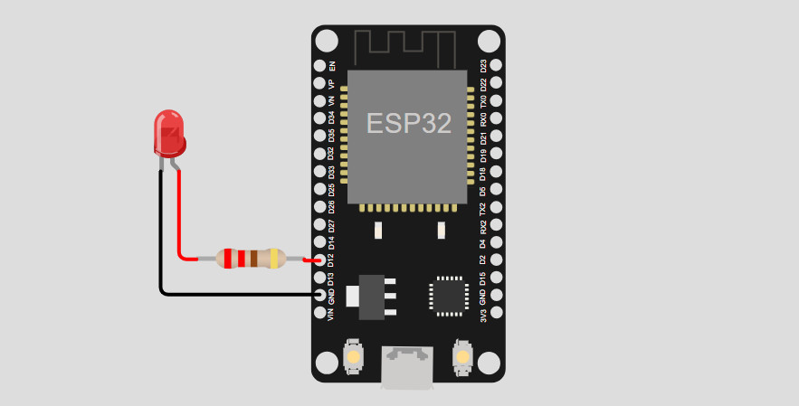
Wiring the LED is pretty simple, and you probably know how to do it.
Simply hook the cathode of the LED (shorter pin) to one of the ESP32’s ground pins. Next, connect the anode (longer pin) to any GPIO pin of your choice. Make sure to use a resistor (e.g., 220Ω) to increase the LED’s lifespan.
ESP32 MQTT Publisher Sketch
Upload the following sketch to the ESP32 with the photoresistor (the publisher):
#include <WiFi.h>
#include <PubSubClient.h>

const char* ssid = "YOUR_WIFI_SSID";
const char* password = "YOUR_WIFI_PASSWORD";
const char* mqttServer = "192.168.178.128"; // IP of the Raspberry Pi
const int mqttPort = 1883;
const char* mqttTopic = "sensors/light";

WiFiClient espClient;
PubSubClient client(espClient);

const int ldrPin = 35; // photoresistor pin

bool lightOn = false; // stores the state of the LED
const int threshold = 2000; // brightness threshold

void setup() {
  Serial.begin(115200);

  // Connect to WiFi
  WiFi.begin(ssid, password);
  while (WiFi.status() != WL_CONNECTED) {
    delay(500); Serial.print(".");
  }
  Serial.println("\nConnected to WiFi");

  // Connect to Mosquitto Broker
  client.setServer(mqttServer, mqttPort);
  while (!client.connected()) {
    Serial.print("Connecting to MQTT...");
    if (client.connect("ESP32Publisher")) {
      Serial.println("connected");
    } else {
      Serial.print("failed, rc=");
      Serial.print(client.state());
      delay(2000);
    }
  }
}

void loop() {
  int lightLevel = analogRead(ldrPin); // read the current brightness

  // If LED is off and brightness is below threshold, turn LED on
  if (!lightOn && lightLevel < threshold) {
    const char* msg = "ON";
    client.publish(mqttTopic, msg); // publish message to topic
    lightOn = true;
    Serial.print("Published: "); Serial.println(msg);
    delay(1000);
  }
  // If LED is on and brightness is above threshold, turn LED off
  else if (lightOn && lightLevel >= threshold) {
    const char* msg = "OFF";
    client.publish(mqttTopic, msg); // publish message to topic
    lightOn = false;
    Serial.print("Published: "); Serial.println(msg);
    delay(1000);
  }
}This sketch connects to your WiFi network and the Mosquitto broker on your Raspberry Pi. Whenever the light level (brightness) is below a certain threshold and the LED of the other ESP is currently turned off, it will send an MQTT message to the topic “sensors/light” to turn the LED on. Of course, it also works the other way around (turn the LED off when the light level is above the threshold).
Make sure to replace the placeholders like ssid, password, and mqttServer with your data!
ESP32 MQTT Subscriber Sketch
Upload the following sketch to the ESP32 with the LED (the subscriber):
#include <WiFi.h>
#include <PubSubClient.h>

const char* ssid = "YOUR_WIFI_SSID";
const char* password = "YOUR_WIFI_PASSWORD";
const char* mqttServer = "192.168.x.x"; // IP of the Raspberry Pi
const int mqttPort = 1883;
const char* mqttTopic = "sensors/light";

WiFiClient espClient;
PubSubClient client(espClient);

const int ledPin = 4;

// Callback function is called when a message is received
void callback(char* topic, byte* payload, unsigned int length) {
  char msg[8];
  memcpy(msg, payload, length);
  msg[length] = '\0';

  if (strcmp(msg, "ON") == 0) {
    digitalWrite(ledPin, HIGH);
  } else if (strcmp(msg, "OFF") == 0) {
    digitalWrite(ledPin, LOW);
  }

  Serial.print("Received LED state: ");
  Serial.println(msg);
}

void setup() {
  Serial.begin(115200);
  pinMode(ledPin, OUTPUT);

  // Connect to WiFi
  WiFi.begin(ssid, password);
  while (WiFi.status() != WL_CONNECTED) {
    delay(500); Serial.print(".");
  }
  Serial.println("\nConnected to WiFi");

  // Connect to Mosquitto Server and register callback function
  client.setServer(mqttServer, mqttPort);
  client.setCallback(callback);

  while (!client.connected()) {
    client.loop();
    Serial.print("Connecting to MQTT...");
    if (client.connect("ESP32Subscriber")) {
      Serial.println("connected");
      client.subscribe(mqttTopic);
    } else {
      Serial.print("failed, rc=");
      Serial.print(client.state());
      delay(2000);
    }
  }
}

void loop() {
  // Listen for messages
  client.loop();
}This sketch also connects to your WiFi network and the Mosquitto broker on your Raspberry Pi. Whenever a message in the topic “sensors/light” is published, this ESP32 will toggle the LED accordingly.
Again, make sure to replace the placeholder values in the sketch!
Testing the Setup
Follow these simple steps to ensure your ESP32 MQTT setup is working correctly:
- Power your Raspberry Pi (or other Linux device) and ensure Mosquitto is running
- Upload the publisher code to one ESP32 and the subscriber code to another
- Open the serial monitor for both boards to observe the communication
- Cover or shine light on the photoresistor to trigger LED changes
If the LED turns on when you cover the photoresistor and turns off when you shine light on it, your MQTT setup works!
Wrapping Up
You’ve now built a simple ESP32 MQTT communication system with two ESP32 boards using a Raspberry Pi MQTT broker. This is a great foundation for smart home projects, sensor networks, or more complex IoT systems.
Next, check out how to secure your MQTT connection with SSL/TLS and authentication!
What would you use MQTT for? Share your ideas in the comments below!
Thanks for reading, happy making!
Links marked with an asterisk (*) are affiliate links which means we may receive a commission for purchases made through these links at no extra cost to you. Read more on our Affiliate Disclosure Page.