The ESP32-CAM is a popular low-cost development board that combines Wi-Fi and Bluetooth connectivity with a built-in camera module, making it perfect for projects like home surveillance, object tracking, and more. However, wiring additional components, like sensors, can be a bit tricky due to the limited number of usable GPIO pins.
In this guide, you’ll find a complete ESP32-CAM pinout diagram, GPIO descriptions, and practical tips to avoid common wiring mistakes.
What is the ESP32-CAM?
The ESP32-CAM is a popular microcontroller development board among hobbyists. It is based on the ESP32-S2 module and features OV2640 camera support, a MicroSD card slot, as well as typical features of the ESP32, like Wi-Fi and Bluetooth.
The ESP32-CAM is especially interesting because it has a built-in camera and MicroSD slot, making it perfect for projects, like building a surveillance camera with face recognition.
Note that the ESP32-CAM does not have a USB port! You’ll ned an external USB-to-Serial adapter to upload code.
Get an ESP32-CAM with USB-to-Serial adapter here*:

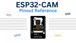
ESP32-CAM Pinout Diagram
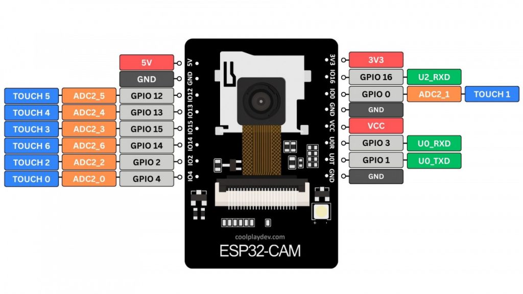
The ESP32-CAM features 16 pins, 10 of which are GPIO pins. In addition, 7 out of the 10 GPIOs are ADC (Analog to Digital Converter) pins, which can be used to read analog signals and detect capacitive touch inputs.
ESP32-CAM Pin Descriptions
Power Pins
Just like most other ESP32 Development Boards, the ESP32-CAM has a 5V pin and a 3.3V pin, which can be used to power the board. The VCC pin, however, should not be used to power the board. Instead, the VCC pin is an output power pin, which usually outputs 3.3V but can be configured to output 5V using the zero-ohm link near the pin.
UART & Flashing
The ESP32-CAM features two separate UART interfaces – UART0 and UART2.
Because the board doesn’t feature a USB port, both pins of the UART0 interface, RX and TX, need to be used for flashing.
To enter flashing mode, GPIO 0 must be pulled LOW (connected to ground).
Sadly, we can only use the receive pin (RX) of the UART2 interface, making it hard to use some UART devices that rely on bidirectional communication.
Flashlight
Most ESP32-CAM modules come with a built-in white flashlight LED located next to the camera lens, and it’s connected to a dedicated GPIO pin that we can use. The LED is very bright and lights up the environment when taking pictures. Of course, you can also use it independently of the camera.
The internal Flashlight is connected to GPIO 4.
Here’s how you can manually turn the ESP32-CAM’s flashlight on:
void setup() {
  pinMode(4, OUTPUT);
  digitalWrite(4, HIGH); // Turn on flashlight
}

void loop() {}Important: Keep in mind that the flashlight pin is hooked up to the DATA1 pin of the SD card.
MicroSD Pins
Here’s how the SD card is connected to the ESP32. You can use these pins freely when not using an SD card.

PWM & I2C
All the available GPIO pins of the ESP32-CAM support PWM (Pulse Width Modulation). However, be aware of conflicts with SD card pins and pins with additional functionality (e.g., GPIO 0, which is used for Boot).
Similarly, all GPIO pins can be used for I2C communication, as I2C is not hardware-defined but can be implemented via software using any two free GPIOs.
Important Notes
Here’s a list of a few things to keep in mind when using the GPIO pins:
- GPIO 0 must be pulled LOW to enter flashing mode
- GPIOs 1 and 3 are used by the serial port (e.g., to flash firmware)
- GPIO 4 controls the onboard flashlight LED
- Not all GPIOs are available when using an SD card (see MicroSD pins)
Wrapping Up
The ESP32-CAM is an impressive little board, but its pin limitations can be confusing at first. If you know the ESP32-CAM’s pinout and which GPIOS are safe to use, you can confidently build camera-powered projects like surveillance systems, AI face detectors, object tracking, and a lot more.
Let me know in the comments what you’re building with your ESP32-CAM!
Thanks for reading!
Links marked with an asterisk (*) are affiliate links which means we may receive a commission for purchases made through these links at no extra cost to you. Read more on our Affiliate Disclosure Page.
Oh my goodness! Incredible article dude! Thanks, However I
am experiencing troubles with your RSS. I don’t know the reason why I am
unable to subscribe to it. Is there anybody else getting the same RSS problems?
Anyone that knows the answer will you kindly respond? Thanx!!
Hey!
I am happy you like the article 🙂
The RSS feed of the site should be available under coolplaydev.com/feed.
You can use this URL with any RSS reader of your choice.
If you still have issues with RSS, let me know!