

Espressif’s own wireless protocol ESP-NOW enables fast, low-power, and direct communication between two or more ESP microcontrollers in different modes without depending on a WiFi network.
In this guide we will cover what ESP-NOW is, how it works, and how to establish a wireless connection between two microcontrollers using the Arduino IDE!
What is ESP-NOW?
ESP-NOW is a wireless communication protocol developed by Espressif, the creator of the popular ESP microcontrollers. Unlike traditional WiFi, this protocol allows devices to communicate directly with each other without the need for a router or an active internet connection.
This so-called peer-to-peer communication is fast and efficient and consumes less power, making it great for IoT applications, remote sensors, and battery-powered devices.
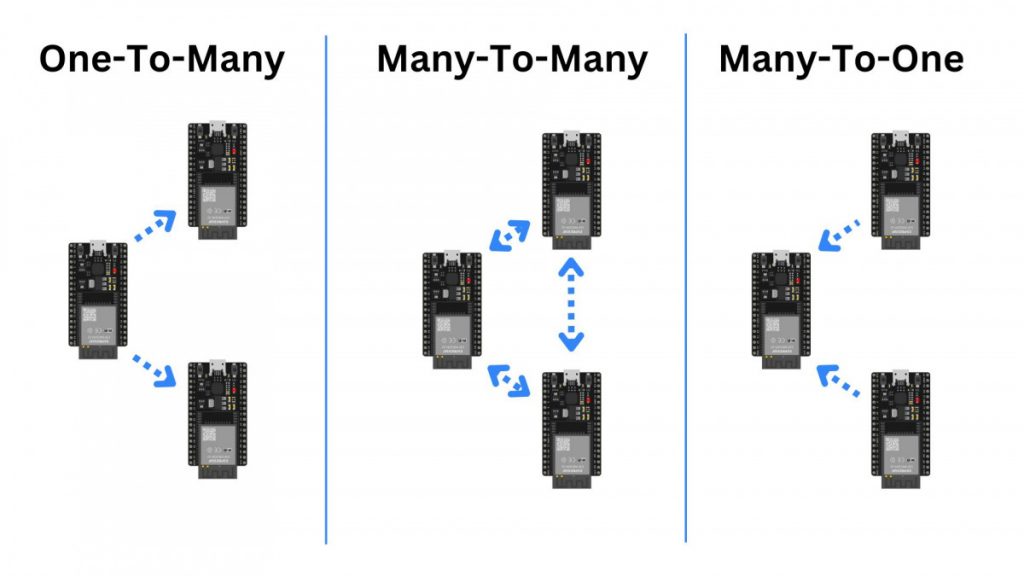
In a network, a microcontroller can act as a transmitter, a receiver, or a transceiver, which can do both – transmitting and receiving.
Additionally, ESP-NOW allows for one-to-many, many-to-many, and many-to-one communication networks.
Which Microcontrollers Support ESP-NOW?
ESP-NOW is supported by the following microcontrollers from Espressif:
- ESP32
- ESP32-S
- ESP32-C
- ESP8266
How Does ESP-NOW Work?
Just like WiFi, ESP-NOW operates on the 2.4GHz frequency band.
However, instead of connecting through a router, devices in an ESP-NOW network can communicate directly with each other.
In this so-called peer-to-peer network, devices need to be paired by their MAC address. If one device in the network loses power, it will automatically reconnect if powered again.
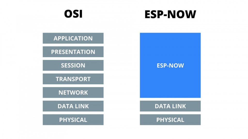
Espressif simplified the communication process by merging the Application, Transport, and Network layers of the traditional OSI Model into a single layer.
Also, there’s no need for packet headers. This allows for faster transmission time because packets don’t have to be packed and unpacked.
Data packets can have a size of up to 250 bytes and can be encrypted if the encryption mode is enabled. To encrypt and decrypt every device in the network needs to know the PMK and LMK keys, which are defined in the code.
Learn more about how the encryption of ESP-NOW works and is implemented in the Arduino IDE in this comprehensive guide.
Frequently Asked Questions about ESP-NOW
Is ESP-NOW faster than WiFi?
Yes, ESP-NOW is faster than traditional WiFi. The way ESP-NOW simplifies the OSI Model and doesn’t require an established connection allows for faster data transmission. However, the protocol is only designed for small data packets which results in a lower bandwidth compared to WiFi.
What is the range of ESP-NOW?
The 2.4GHz ESP-NOW communication protocol can achieve a range of approximately 200 meters in an open field.
How many ESP micronctrollers can be in one network?
An ESP-NOW network can consist of up to 20 paired ESP32s or up to 10 paired ESP8266.
When broadcasting a message, there’s no limit of how many devices can receive that broadcast message.
Can ESP-NOW work without WiFi?
Yes absolutely! In fact, ESP-NOW is a communication protocol of its own. Compared to WiFi, there’s no need to establish a connection between devices before sending data.
Can ESP-NOW work without WiFi?
Yes, you can use ESP-NOW and Wi-Fi simultaneously on ESP32 devices, but there are some limitations to consider. The ESP32 supports running both protocols simultaneously by using its dual-core architecture and Wi-Fi coexistence features. This allows you to, for example, send data using ESP-NOW while maintaining a Wi-Fi connection to a router or an access point.
Does ESP-NOW work on ESP8266?
Yes, ESP-NOW also works on ESP8266 boards!
Check this detailed article about the differences between ESP32 and ESP8266.
Getting Started With ESP-NOW Using The Arduino IDE
Let’s apply what we just learned!
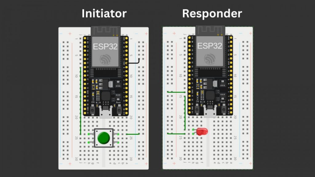
Therefore, we are going to take two ESP32s. One of them is the Initiator (Master). It has a push button attached to one of its GPIO pins. The other ESP32, the Responder (Slave), has an LED that will be turned on or off if we press the button on the Initiator.
For transmitting the data whether the LED should be on or off, we use ESP-NOW.
If you need help setting up the Arduino IDE for use with ESP32 boards, check out this comprehensive guide.
Getting the MAC address of a device
Before two ESP microcontrollers can communicate with each other, they need to know each other’s MAC addresses.
We can find out the MAC address of an ESP32 microcontroller using the following code in the Arduino IDE:
				#include <WiFi.h>
#include <esp_wifi.h>

void getMacAddress(){
  uint8_t baseMac[6];
  esp_err_t ret = esp_wifi_get_mac(WIFI_IF_STA, baseMac);
  if (ret == ESP_OK) {
    Serial.printf("%02x:%02x:%02x:%02x:%02x:%02x\n",
                  baseMac[0], baseMac[1], baseMac[2],
                  baseMac[3], baseMac[4], baseMac[5]);
  } else {
    Serial.println("Failed to read MAC address");
  }
}

void setup(){
  Serial.begin(115200);

  WiFi.mode(WIFI_STA);
  WiFi.STA.begin();

  Serial.print("MAC Address: ");
  getMacAddress();
}

void loop(){
}
Upload the code to your ESP32 and watch the serial monitor for its MAC Address.
For more information on how to read the MAC address of your ESP32 and even change it, check out this post!
Implementing Communication between two devices
To control the LED from the Responder using the Initiator, we need to tell the Initiator the Responder’s MAC address.
Because our example is unidirectional communication, we only need the Responder’s MAC address.
Initiator (Master) Code
The following code sends a boolean value, whether the LED should be on or off, whenever the attached push button is pressed.
Note that if you want to send data to multiple responders without pairing, you can send the same data to all of them by using the broadcast MAC address.
				#include <esp_now.h>
#include <WiFi.h>

// MAC Address of the responder (Broadcast Address: {0xFF, 0xFF, 0xFF, 0xFF, 0xFF, 0xFF})
uint8_t receiverAddress[] = {0xFF, 0xFF, 0xFF, 0xFF, 0xFF, 0xFF};

// Structure example to send data
// Must match the receiver structure
typedef struct struct_message {
  bool enable;
} struct_message;

struct_message myData;

esp_now_peer_info_t peerInfo;

const int buttonPin = 33;

// callback when data is sent
void OnDataSent(const uint8_t *mac_addr, esp_now_send_status_t status) {
  Serial.print("\r\nLast Packet Send Status:\t");
  Serial.println(status == ESP_NOW_SEND_SUCCESS ? "Delivery Success" : "Delivery Fail");
}

void setup() {
  // Init button port
  pinMode(buttonPin, INPUT_PULLUP);

  // Init Serial Monitor
  Serial.begin(115200);

  // Set device as a Wi-Fi Station
  WiFi.mode(WIFI_STA);

  // Init ESP-NOW
  if (esp_now_init() != ESP_OK) {
    Serial.println("Error initializing ESP-NOW");
    return;
  }

  // Once ESPNow is successfully initialized, we will register the callback function to
  // get the status of Trasnmitted packet
  esp_now_register_send_cb(OnDataSent);

  // Register peer
  memcpy(peerInfo.peer_addr, receiverAddress, 6);
  peerInfo.channel = 0;
  peerInfo.encrypt = false;

  // Add peer (pair device)
  if (esp_now_add_peer(&peerInfo) != ESP_OK){
    Serial.println("Failed to add peer");
    return;
  }
}

void loop() {
  // Read button input
  if (digitalRead(buttonPin) == HIGH) {
    // Set value to send
    myData.enable = !myData.enable;

    // Send message via ESP-NOW
    esp_err_t result = esp_now_send(receiverAddress, (uint8_t *) &myData, sizeof(myData));

    // Wait until button is released
    while (digitalRead(buttonPin) == HIGH);
    delay(500);
  }
}
Responder (Slave) Code
The Responder does not need to know the MAC address of the Initiator because it’s not sending any data.
In the following code, we turn on or off the LED according to the data we received.
After receiving data, we call a callback function OnDataReceived that switches the state of the LED.
				#include <esp_now.h>
#include <WiFi.h>

// Structure example to receive data
// Must match the sender structure
typedef struct struct_message {
    bool enabled;
} struct_message;

struct_message myData;

const int ledPin = 13;

// callback function that will be executed when data is received
void OnDataRecv(const uint8_t * mac, const uint8_t *incomingData, int len) {
  memcpy(&myData, incomingData, sizeof(myData));
  // Turn LED on/off
  digitalWrite(ledPin, myData.enabled);
}

void setup() {
  pinMode(ledPin, OUTPUT);

  // Initialize Serial Monitor
  Serial.begin(115200);

  // Set device as a Wi-Fi Station
  WiFi.mode(WIFI_STA);

  // Initialize ESP-NOW
  if (esp_now_init() != ESP_OK) {
    Serial.println("Error initializing ESP-NOW");
    return;
  }

  // Once ESPNow is successfully initialized, we will register our callback function to
  // get recv packer info
  esp_now_register_recv_cb(esp_now_recv_cb_t(OnDataRecv));
}

void loop() {

}
Conclusion
ESP-NOW by Espressif is an efficient and lightweight alternative to traditional wireless communication protocols like WiFi.
The microcontrollers in a network are connected directly to each other, making up a peer-to-peer network.
In this guide, we’ve explored what ESP-NOW is, how it works, and how to get started with it using the Arduino IDE. With this knowledge, you can create fast and reliable communication networks for your projects. Whether you’re building a smart home system or a remote monitoring setup.
Next, you should explore how to encrypt ESP-NOW communication and how to decide between ESP-NOW and Bluetooth.
Consider sharing this article and leaving a comment!
Thanks for Reading and Happy coding!